Monday, May 18, 2015

Lab 21: Galvanometer, Faraday's Law, Lenz's Law

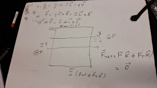
Force was derived as a function of two currents through previous equations. This picture explains that if two currents are going in the same direction, the the force is going inwards, likewise, when two currents are in opposite directions, the force goes outwards.
 This picture shows an electric pole, there is no force because the two wires produce alternating currents, meaning that they will be continuously canceling each other.

 This graph was determined by Professor Mason, he calculated the magnetic field in the class as a function of time.

 We worked with the magnetic field at the center of a current loop lab, this lab consisted on measuring the magnetic field change due to a number of loops. First of all, we used a magnetic field sensor, and calibrated it in order to eliminate the effects of the Earth's magnetic field. Then we used copper wire to wrap a test tube to create the loops, and finally the magnetic field of each loop was calculated through logger pro.
 This picture shows the magnetic field due to a certain amount of copper loops, as we can see, the magnitude of magnetic field is directly proportional to the number of loops, when the current and voltage are constant.

 A galvanometer is an instrument that detects electric current. Professor Mason showed us that when a magnet is pull out and push in into a copper wire with many loops, it produces an induced electric current, and the faster it is pulled or pushed, the current increases. 
 These are factors that help maximize the current. Another important factor is the area between the magnet and the number of loops, if its smaller, current increases.

This experiment proves Faraday's law, Professor Mason added a coil that is insulated, the coil is placed above the previous coil, there is no direct electric contact; however, the alternating magnetic field induces an alternating current which lights up the bulb. If the coil is moved up, it gets dimmer. If the magnetic field is increased, even though the coil is not touching the metallic bar, if also lights up, since the magnetic field is going upwards, it is possible that it reaches the coil.
After this, Professor Mason added a copper coil, the magnetic field of this coil points in the opposite direction compared to the first coil. As the magnetic field going upwards increases, the copper coil starts to levitate.
Then, Professor Mason added an aluminum coil, the silver coil levitated higher because the density was lower than the copper coil.
The next one was a steel ring with a gap in between, which means that current can't flow, so nothing will happen.

The next experiment is applied to Lenz's Law, Professor Mason dropped two magnets through two different tubes, one made of aluminum and another made of glass. We observed that the magnet running inside the glass landed way before the aluminum did because for the aluminum case there was a change in magnetic flux, as the magnet was sliding down it generated a current moving counterclockwise in the aluminum that slowed the magnet down since there was a magnetic field going up as a consequence. This was not a magnetic effect because Aluminum is not a magnetic material, however, aluminum is a conductor, so it was the current that effected the magnet.

Here we derived an expression for emf by using magnetic flux and magnetic field equations. 
We then drew the graphs of magnetic field and emf as a function of time. The magnetic field has a sine function whereas the emf has a negative cosine function.

Sunday, May 17, 2015

Lab 19: Magnetic Field and Magnetic Force

 Here, Professor Mason put iron powder into the magnetic bar at random locations, the interesting thing was that the iron powder automatically filled in the direction of the magnetic field, which goes from the north pole to  the south pole.
 Similarly, we used a compass to show the same behavior as the iron powder. We placed the compass on every place surrounding the magnetic bar, and the north direction of the compass always pointed in the direction of the south on the magnetic bar because they attract each other, we signaled it with arrows as we advanced. Also, when we placed the compass at the north pole, it didn't pointed to the south direction, because the repelling force was stronger than the attractive force.

 This is a big magnet. Professor Mason explained that when a magnetic domain is cut in half, then there is no magnetic field, which causes the flux to be zero, and are considered magnetic monopoles, which in reality they don't exist. To prove this, he removed the north pole of the big magnet, the removed piece was not a magnetic monopole because is also has a south pole since all cut poles come in groups, meaning a south and a north.
 We drew surfaces on the magnetic lines. Two of our surfaces had zero flux, which means there is no magnetism. One of the surfaces had 5 magnetic lines going in, which means the magnetic field is negative.
 These were some exercises using the right hand rule.
 Through some unit calculations, we found that the unit for magnetic field is N/A.m
 We calculated the acceleration of the proton to be 3.74x10^11 m/s^2 in the same direction as the force.

 First, we use the force equal the centripetal acceleration. Since we were given a frequency, we use the angular velocity in our calculations. So that, B = mw/q, in order to find the magnetic field of the given problem.
Professor Mason put a string in between the magnet, when he turn the device on, the string was moving up and down because energizing the string causes the electrons to collide.

 We learnt something important, when dealing with protons, we use the right hand rule, and when dealing with electrons, always use the left hand rule.

Using the right hand rule with both currents, we found that the net force equals zero.

 The net force in this case is also zero, because the direction of the force is always perpendicular to the displacement of a magnetic field.

We were asked to find the net magnetic forces on a semicircular wire divided into 15 segments with constant magnetic field, radius and current. Excel only calculates radians, for this reason I converted degrees into radians. The net force was calculated with the formula F = IBLsinθ. The force is much more smaller for some segments than for other segments because of the angle it has with respect to the magnetic field. When the angle is nearly perpendicular to the magnetic field, the force is nearly zero, and if the force is parallel to the magnetic force, then it is at its maximum.

Lab 18: CRT, Oscilloscope and Mystery Box

 Professor Mason set up a CRT (Cathode Ray Tube) , which is a vacuum tube that contains electron guns and focusing plates at the inside. By adjusting the voltage, it is possible to stir the light beam in the direction of the focusing plates; however, depending on the charge of each plate the graph varies.

 Using an oscilloscope, Professor Mason explained that if we change the period or frequency too much, it produces a dot going horizontally until the point it becomes a straight line because its going too fast. As shown in the below picture.
 Here, we added a battery, the result was that the voltage increased, so the graph moved vertically up.
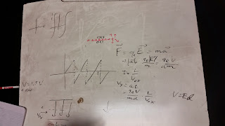
 We derived acceleration by using the second law of Newton (F = ma) and Lorentz force (F = qE). Also we derived the vertical component of velocity. Vy = at. We know that time is just distance over velocity. So, we plug in acceleration and time into the Vy function.

 We used a function generator along with a speaker to test the sounds it produces when changing the frequency and voltage. First test case was sine wave set at 96 Hz. It produced a low deep hum sound. Second case was triangle and square wave, the triangle sound even deeper than the sine wave; however, the square one has a high pitch bee sound. When increasing the frequency, the pitch increases as well. When increasing the amplitude, it makes the sound louder.
Sine wave output.
 Square wave output.
 Triangle wave output.

Here, we can see the noise showing on top of the DC power supply that output 5V with triangle waves. This noise is periodic with period of 60Hz. AC coupling lets you take a DC signal in order to see if there is noise by zooming in.

 Professor Mason graphed a circle using two function generators at the same frequency.

Mystery Box
Using the mystery box, we plug in Black and Red, and we found out that the red one is an alternating current by looking at the graph.
 Black and Yellow has no changes, meaning that yellow is direct current because it shows a straight line without holes.
 Black and Blue gives 5V, also Blue is direct current.
Black and Green gives 8.5V, Green is direct current.
We plotted this graph to show the voltage of each color. There was a mistake with the names, blue and green supposed to be switched.

Lab 17: Charge and Decay in Capacitors

First thing we did today was to charge and discharge capacitors, then we worked on the charge build up and decay in capacitors lab. To discharge a capacitor, we just connect the capacitor with the bulb holder, and to charge it, it must be connect to a voltage supply. When charging a capacitor, the brightness of the bulb decreases over time. We learnt that if the capacitance decreases, then the times it takes to charge also will decrease, and vice versa. Also, this charging time is also known as tau, which is the time it takes a capacitor to charge up to 37%.
Our graph of brightness vs time, indicates that the brightness of the bulb has an inverse relation with the capacitor because over time it gets dimmer.
Then our group used 3 batteries in series with 1 capacitor while the other group used 2 batteries in series with 1 capacitor, both groups were supposed to calculate the respective voltage. After knowing each voltage, we used three batteries in series connected with two capacitors in series in order to predict the final voltage. The final voltage resulted to be just the mean value of the two previous voltages.

 We started working on the quantitative measurements on an RC system lab. We grabbed 5 capacitors of 1000uF for this experiment. First we fully charged the capacitors with 3 batteries, then we graph the potential vs time using logger pro when we closed the circuit (discharging graph). We also graph the potential vs time when the capacitors were charging. Both graphs resulted to be exponential functions. The equation for discharging capacitor is V(t)=Voe^(-t/τ) and for charging capacitor is
V(t)=Vo(1- e(^-t/τ)).


Using the formula given by logger pro, we verified that the units where correct. Then using the formula τ = RC, we found the units for tau, which was supposed to be seconds.

Professor Mason showed us that if a capacitor is overcharged in the wrong direction, it will explode. Here is the capacitor after the explosion.

This is the time it takes the capacitor to charge.
This is the time it takes the capacitor to discharge.