Tuesday, June 9, 2015

Lab 25: AC RC and RLC Circuits

At the beginning of the class, professor Mason start explaining that Ohm's law also applies in AC circuits, as it does in DC circuits. The difference is that in AC circuit there are three resistance, created by resistors, capacitors and inductors. This total resistance is called impedance, categorized by the letter Z. In RC circuits, the Z = sqrt(R^2+XC^2). 
 We know that Vrms = ZIrms from Ohm's law, and that XC= 1/ωC, we solve for Irms, and found out that if the angular frequency doubles it causes the root mean square current to double.

 Here is the set up of RC Circuit in AC. We used the RLC Circuit board, we connected a resistor and capacitor to the function generator, and the voltmeter and current sensor to logger pro. In logger pro, we zero out both sensors, and set the sampling rate at 5000 with a frequency of 10Hz. And graphed the V vs T, and I vs T.
 We used 100 ohm resistor and 100μF capacitor, we found Vmax and Imax by looking at the graphs. Then impedance was calculated through the formula Z = Vrms/Irms. Our percent error was 0.6%. We also found the phase change between the V(t) and I(t) to be -1.5 rad by using ϕ = arctan(-XC/R). We also did the experiment with a frequency of 1000Hz, for this case, logger pro does not allow high sampling per second when two sensors are connected at the same time, so we disconnect and record the samplings with only one sensor because logger pro can sample up to 50000 per second, our percent error turn out to be 1310%, a really big error. Finally, we repeated the experiment one more time with a frequency of 100Hz. And found that the phase change was -1.00 rad.

 In this photo we calculated the experimental phase change.

We started working on Resonance in RLC circuit lab. In RLC, Z = sqrt(R^2 + (XL - XC)^2). When the impedance is minimized the current is maximize, for this reason there exists a frequency called resonance frequency, it occurs when f = 1/(2pi(sqrt(LC))).
 We calculated the resonance frequency of the given circuit to be 5033Hz. Then we used a resonance frequency of 3kHz, we calculated the capacitive reactance and inductive reactance. With these values, we were able to compute the value of Irms in order to calculate the power dissipated by the resistor using P = Irms^2*R.

 For this experiment, we used the RLC circuit board, inductor, function generator and a multimeter. The goal was to measure the resonance frequency at which maximum current occurs. We used previous values when we used a 55 turn inductor. The inductance calculated was 324μH and the capacitance was 470μF, with these values the resonance frequency is 408Hz.
The theoretical impedance is Z = R, and for the experimental impedance we used Vrms and Irms.

Lab 24: Alternating Current

We started the day by doing the Alternating Currents and Voltages lab. In this lab we used the RLC Circuit Board. For the first part, we set up an AC circuit with the 100ohms resistor on the RLC board, voltmeter and ampmeter, connected to the function generator and logger pro. We zero both meters, and graphed voltage vs time and current vs time. 
In AC circuit the voltage and current vary sinusoidally with time.
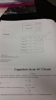
Here are our results. The experiment was done 5 times. We calculated Vmax by looking at statistics of the graph. For Vrms we use Vrms = Vmax/root(2). For theoretical Vrms we used the same formula, but the Vmax was the voltage from the function generator. Then for the percent error, we used 
Percent error = (theoretical- experimental)(100)/(theoretical). We perform the same steps to find Imax, Irms, and percent error. Irms = Imax/root(2). 

 Here, we draw voltage and current vs time in the same plane, and something important to notice is that both sinusoidal graphs have different amplitude, the amplitude of I(t) is bigger by a factor of ωC.


In this photo we found Irms with given capacitor, frequency and Vrms. We said that Irms = Vrms /XC, where Xis the effective ohmic resistance of the capacitor or also known as capacitive reactance, and XC = 1/ωC, and ω = 2pi*f. We plug everything in and found that Irms = 0.06A.

 We repeated the experiment, but this time instead of using the resistor, we connected the circuit into the capacitor. Once again, the Imas and Vmas were taken from the graphs in order to find Irms and Vrms. For XC theoretical and experimental, we used X= Vrms / Irms , also we found the percent error of the capacitive reactance, which was 11.5%.


We repeated the experiment one more time, and instead of using capacitor we connected the circuit to an inductor. An inductor creates a resistance within an AC source referred as XL which equals ωL, this formula was used to calculate the theoretical value. For the experimental value we used 
XL = Vrms.exp / Irms.exp ,and our percent error turn out to be 7.9%.

Lab 23: RL Circuits

We were give a voltage vs time graph, and asked to graph current vs time in an inductor. First we  said that ε = flux / I, we solve for current and then take the derivative so that we could see the relation between I and ε. We realized that they have inverse relationship, so the graph should also be inverse with respect to time. Then we were given a resistor, and we determined the corresponding magnitude of the resistor by looking at the colors it has. In this case, it was brown, black, and brown. We used the resistor-color table for this. 
 Then we were given an inductor, with the given variables we used the equation L = (μ0AN^2)/l, to calculate its inductance. Then we used the formula Rcoil = pL/A to calculate the resistance of the copper coil, for the area we used the cut or cross sectional area. Then we calculated the time constant with the inductance previously calculated and the 150ohms resistor.

We start working on the lab manual. This lab consisted on a circuit using a oscilloscope, function generator, resistor and inductor.
On the function generator, we set the frequency at 40kHz and the voltage at 2V, and we used the square wave form to graph whats on the picture.
 We used an inductor with 55 turns, and measure its theoretical inductance, which was 190μH. From the given graph, we measure the half-time t1/2  of the decay of the induced emf. In order to get a precise value, we adjusted the horizontal and vertical scales so that a single decay fills the oscilloscope display. We found that the half-time is 1.5μs. Then using using the formulas τ = L/R and τ = t1/2 /ln2, we equate them in order to find the experimental inductance, which turn out to be 324μH, then using this inductance, we calculated the corresponding turns, which was N = 72 turns.

To conclude the class, we worked on a RL Circuit problem. We were given the values of inductor, 2 resistors, and voltage supply. To find the time constant when the switch is first closed, we used the formula τ = L/R, where L = 35mH and for R we used the 120ohms resistor since the switch is closed. Then as the switch opens again, we were asked to find the current. Since the resistors are in parallel, the voltage across each resistor should be 45V, so we used Ohms law I = V/R to calculate the current in the 730 resistor. For the 120 resistor we cannot only use Ohms law since it is in series with an inductor, so we used I = Imax(1-e^(-t/τ )), where Imax can be found using Ohms law. The voltage drop for both resistor can be calculated by using V = IR. For part d, we used the same formula as when we calculated the current in the 120 resistor, but we solved for the time using V = 34V. Lastly, the energy dissipated can be calculated by using E = (1/2)LI^2.